Starlink on a Sailboat: Setup, Power & Mounting
Starlink on a Sailboat: Setup, Power, Mounting (and Fewer Dropouts)
Starlink on a sailboat is one of those upgrades that feels like cheating—until you install it like a house router, mount it behind the backstay, and wonder why your Zoom call dies every time you tack. The good news is that most “Starlink problems” afloat are really boat problems: obstructions, voltage drop, wet lockers, vibration, and unrealistic duty cycles.
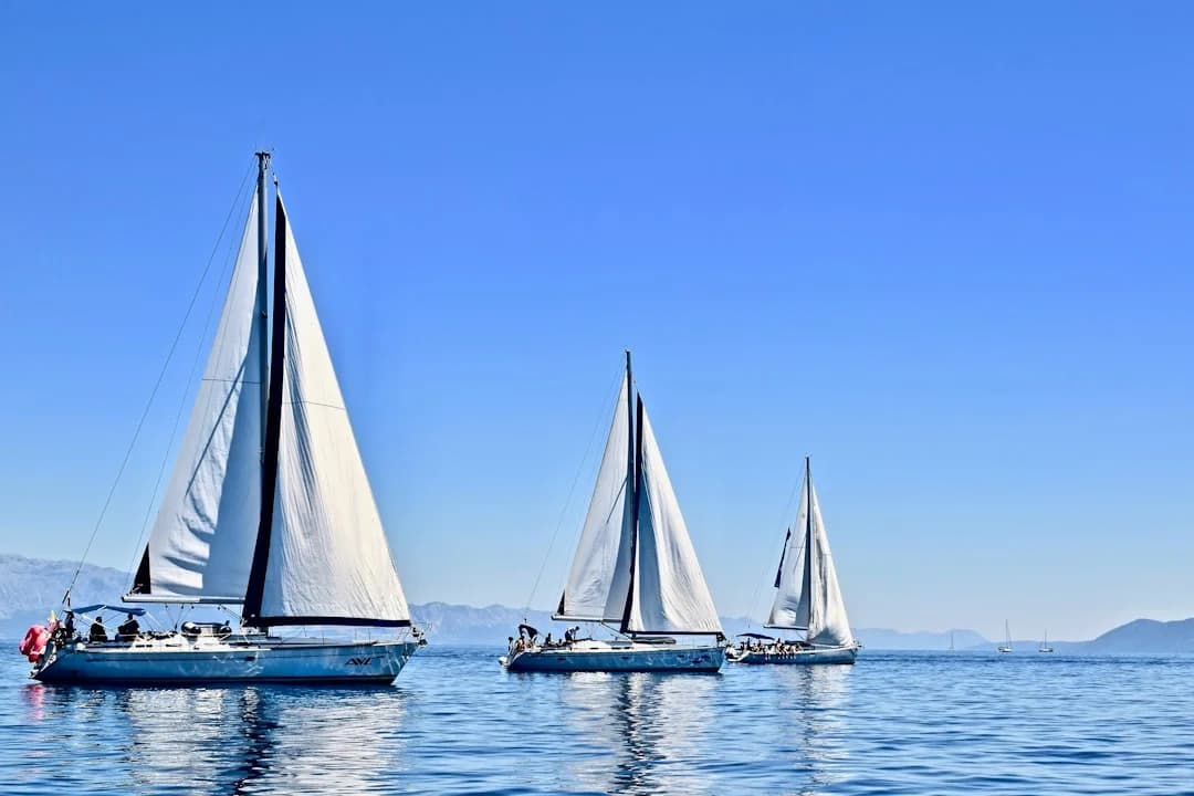
Photo by Karla Car on Unsplash
This checklist-driven article breaks the job into three real decisions: hardware + plan, power path, and mounting geometry. If you get those right, the rest is just drilling holes (carefully) and pretending you enjoy crimping lugs.
Starlink on a Sailboat: Hardware and Plan Selection
Choosing the right terminal and plan is less about bragging rights and more about matching your sailing profile and power system. Coastal cruisers anchored near towns deal with congestion and obstructions, while offshore passagemakers deal with motion, windage, and day-after-day energy math. The wrong combination can be expensive and still flaky.
Standard vs Flat High Performance (Marine-Style) Terminals
The Starlink Standard kit (often used with Roam) is the value choice at roughly $299–$599 and typically draws about 50–75 W steady-state with short peaks around 100+ W depending on conditions and heater behavior. On many sailboats that’s acceptable—until you try to run it 24/7 on modest solar, or you mount it where the rig blocks 5–10% of the sky. Standard works well for anchoring, coastal hops, and “check in twice a day” passagemaking.
The Flat High Performance terminal is the hard-nosed option when motion tolerance and consistency matter, especially near busy coasts. It’s priced like marine gear because it is: expect $1,999–$2,500 hardware, and power commonly 110–150 W typical use (with higher peaks/heater draw). If you’re doing real work offshore, taking calls under way, or operating around higher-latitude weather, it can be worth it—if your alternator and solar budget agree.
Starlink Mini on a Boat: Use Cases and Tradeoffs
The Starlink Mini is the “energy-and-simplicity first” play at around $399–$599 hardware, and it shines on smaller boats or tight electrical budgets. Think 30–38 foot cruisers with 12 V systems, modest 200–400 W solar, and no appetite for running an inverter all day. The tradeoff is typically less margin in rough conditions and less tolerance for compromised mounting locations.
Mini also rewards a sailor’s habit of shutting things off. If you’re happy with “connect, sync, send, disconnect,” it can be the most civilized way to carry Starlink without turning your battery monitor into a horror story.
Roam vs Priority/Maritime: Network Priority and Coverage
Plans are where people get surprised. Roam is usually $150–$200/month and is effectively best-effort data, meaning your speeds and latency can vary wildly near congested coastlines and busy anchorages. Many boaters see ~25–150 Mbps down and ~5–25 Mbps up near coasts, but that range is a distribution, not a promise.
Priority/Maritime-style tiers are more like $250–$1,000+/month depending on region and included priority GB. The practical difference is “network priority maritime plan” behavior: priority data generally holds up better when the network is busy, which often matters more than peak Mbps. My rule is simple: if you need reliable calls and VPN during prime-time coastal congestion, budget for priority.
A decision matrix that actually works: pick a terminal + plan, then sanity-check it against 12 V vs 24 V, your battery chemistry, and your duty cycle (always-on vs work-hours). If you can’t power it cleanly, you’ll never get stable performance.
Practical tip: Before you buy the “best” terminal, calculate your daily Wh budget and decide if you’ll run Starlink 24/7, work-hours only, or on-demand. Hardware is a one-time pain; power is a daily argument.
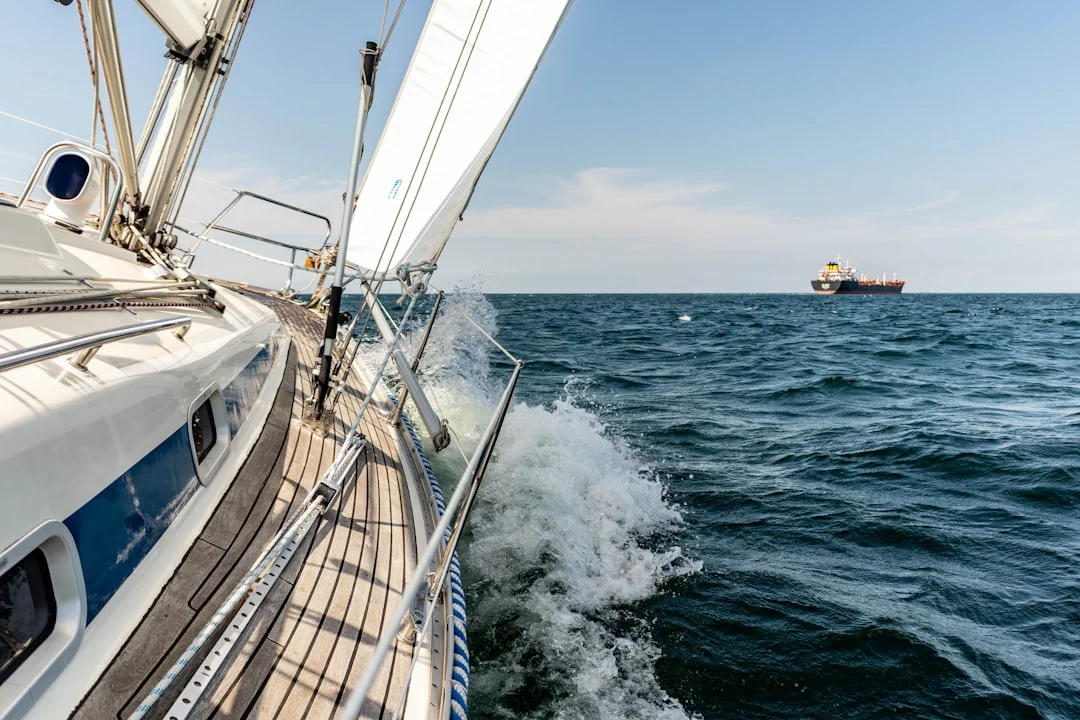
Photo by Michael Held on Unsplash
Real-World Speeds Offshore: What to Expect and Why
Starlink speeds offshore are real, but they’re not magic, and they’re not fixed. The biggest drivers are plan priority, congestion, and the unglamorous reality of sailboat geometry: your mast is a dropout generator. For work use, “peak download” is far less important than stable latency and low packet loss.
Speed and Latency Ranges by Scenario (Anchor, Coastal, Passage)
At anchor near populated coasts on Roam, many users report ~25–150 Mbps down and ~5–25 Mbps up, with latency often ~25–60 ms when things are favorable. Move into a crowded marina or a popular anchorage at 1900 local time, and performance can sag—especially on best-effort plans. Priority data typically improves consistency during those congested windows.
Offshore, you may see excellent throughput in bursts, but you’ll also see more variability in backhaul and handoffs. Latency can stay in that 25–60 ms range when geometry is good, but it can jump during satellite handoffs or when your dish keeps reacquiring due to obstructions. That’s when video calls start to feel like a hostage negotiation.
Dropouts: Obstruction, Handoffs, Heel, and Rig Shadow
On a sailboat, dropouts are usually not “bad service,” they’re partial sky blockage. The rule of thumb I’ve seen play out repeatedly: 5–10% obstruction in the clear-sky view can cause noticeable real-time call drops. It doesn’t take a cliff or a building; it takes a mast, boom, backstay, solar bimini frame, or radar pole in exactly the wrong place.
Heel and pitching make it worse because the antenna’s sky window changes constantly. A mount that looks perfect at the dock can fail on passage when you’re heeled 15–25° and hobby-horsing. The more consistent your view of the sky dome, the fewer handoff-related interruptions you’ll suffer.
Testing Method: Measuring Throughput vs Usability (VoIP/VPN)
Don’t test Starlink afloat like you test home broadband. Do three checks: (1) use the clear view of the sky obstruction map in the Starlink app, (2) run 10–15 minute throughput windows (Speedtest or iPerf), and (3) validate usability with a real call—Wi‑Fi calling, VoIP, or a VPN session. A 200 Mbps spike doesn’t help if your packets are dropping during handoffs.
I also recommend testing on different headings at anchor. Swinging on the hook rotates obstructions through the antenna’s view, and that’s where you discover your “perfect mount” is only perfect on one bearing. If you’re planning routes and comms windows, check the nautical miles for your planned route so you can estimate time underway and decide when you’ll actually need real-time connectivity.
Practical tip: For work calls, prioritize low packet loss and stable latency over peak Mbps. A clean sky view fixes more “internet problems” than upgrading plans.
Power Consumption on a Sailboat: Hourly and Daily Budgets
Power is where Starlink becomes a real marine system, not a gadget. The steady draw looks manageable until you multiply by 24 hours, then add conversion losses, then remember you still want lights, autopilot, nav, refrigeration, and the occasional morale-boosting kettle. The math doesn’t care about your optimism.
Typical Draw: Standard vs Flat High Performance vs Mini
For budgeting, treat Starlink Standard as 50–75 W steady-state with short peaks around 100+ W depending on temperature and heater behavior. In real boats, those peaks matter because voltage sag and long cables cause brownouts and reboots. If you’ve ever watched a router reboot right as you send a critical email, you’ll understand why sailors become boring about electrical design.
Flat High Performance is commonly 110–150 W typical use, again with higher peaks. That’s not “a bit more,” it’s “this is now one of the larger continuous loads onboard.” If you run it through an inverter, it becomes even more expensive in energy terms.
Mini varies by usage pattern and settings, but the strategic point is it generally supports a low-energy philosophy better than the higher-power terminals. If your boat lives on 400 W solar and careful habits, Mini aligns with reality.
Daily Energy Math: Wh, Ah, and What It Means for Lithium Banks
Here’s the number that should be taped to your electrical panel: 75 W × 24 h = 1.8 kWh/day. On a 12 V system that’s roughly 150 Ah/day (1,800 Wh ÷ 12 V). On 24 V it’s about half the current for the same wattage, which makes wiring and voltage drop less painful.
Now compare that to a common cruising bank: 300 Ah LiFePO4 at 12.8 V nominal ≈ 3.84 kWh. A 1.8 kWh/day Starlink load is about 47% of that bank each day if you don’t replenish. Lead-acid fares worse because you don’t realistically use 100% of capacity, and voltage sag punishes electronics earlier.
Solar replenishment is the usual reality check. A 400 W array averaging 200 W for 6 hours yields about 1.2 kWh/day, which is often short of always-on Starlink plus normal hotel loads. If you’re offshore for several days, you’ll need alternator time, wind/hydro, or a shorter duty cycle.
Duty-Cycle Strategies: Always-On vs Work Blocks vs On-Demand
I see three workable profiles aboard cruising boats. Always-on is luxurious, but it’s a power plan, not a settings toggle: expect 1.8 kWh/day at 75 W before losses, and more if you’re on a higher-draw terminal. It’s viable on bigger boats with big charging sources, or on boats that motor a lot (whether they admit it or not).
Work-hours-only is the sweet spot for many liveaboards. If you run it 8 hours/day at 75 W, that’s 0.6 kWh/day, roughly 50 Ah/day at 12 V. That’s a completely different universe for a solar-driven boat.
On-demand is best for passagemaking. Turn it on for weather files, messages, a short call window, then shut it down. Your crew will complain for a day, then they’ll rediscover books and cockpit conversations, and you’ll stop chasing electrons at midnight.
Practical tip: If you’re not sure which duty cycle you’ll use, design your wiring and mounts for always-on, then operate like a realist offshore. It’s easier than rebuilding later.
Powering and Wiring: Inverter vs Direct DC (ABYC/ISO)
If you want Starlink to behave offshore, give it clean power. That means stable voltage at the device under peak load, proper overcurrent protection, and wiring sized for real run lengths. This is straight out of ABYC E-11 (and ISO 10133/ISO 13297 for international boats), with the added spice of wet lockers and long cable runs.
Inverter Feed: Simpler, But Quantify Losses and Idle Draw
Using the supplied AC power supply via a pure sine inverter is the simplest approach. The trap is that you pay for it twice: inverter efficiency and inverter idle draw. At these loads, a reasonable assumption is ~85–92% efficiency, so a 75 W AC load becomes roughly ~82–88 W from the batteries.
That doesn’t sound terrible until you leave the inverter on 24/7 and its idle draw adds another 10–30 W depending on model. Now your “75 W Starlink” can quietly become a 100+ W continuous drain. For some boats that’s acceptable; for many it’s the difference between calm monitoring and obsessive generator rationalization.
Direct DC and DC-DC Conversion: Efficiency and Stability
Direct DC is usually the better marine solution if you do it properly. A quality DC-DC converter in the 150–300 W class typically costs $30–$180, and it can provide stable output during battery voltage swings. Put it close to the load path you control, with short, well-sized conductors on both sides, and you reduce reboot risk.
Placement matters: mount the converter in a dry interior space near your DC distribution, not in the wet cockpit locker next to the spare anchor rode. Add drip loops, strain relief, and service access. If you must place electronics in a damp space, use an enclosure rated to IEC 60529 IP65+, because “splash-proof” is not a specification.
Voltage Drop, Wire Gauge, and Fusing for Long Runs
Voltage drop is the silent killer on boats because runs are long. A typical nav-station-to-stern-arch run is 5–15 m one-way, and ABYC voltage-drop targets often use 3% for critical loads and 10% for non-critical. At 12 V, 3% is only 0.36 V, which disappears quickly at 12.5 A loads.
Current draw is your enemy: 150 W ≈ 12.5 A at 12 V, but only ≈ 6.25 A at 24 V. That’s one reason serious offshore boats often prefer 24 V house systems, especially for long runs to arches and masts. Even on 12 V boats, you can reduce issues with heavier gauge cable, shorter runs, or moving the conversion closer to the source.
Build a dedicated “comms” branch circuit: a proper disconnect, overcurrent protection sized to protect the conductor per ABYC E-11, chafe protection, and secure support along the run. If you’re not comfortable with this, budget a marine electrician at $120–$200/hour, because intermittent comms are annoying and electrical faults are worse.
Practical tip: Design for peak current, not average. Brownouts and nuisance reboots usually happen during brief peaks, not steady cruising loads.

Photo by Markos Mant on Unsplash
Best Mounting Locations: Clear Sky, Low Windage, Serviceable
Mounting is where most Starlink installs win or lose. Height helps, but geometry matters more: you want the widest unobstructed dome of sky with minimal rig shadow as the boat swings and heels. You also want a mount that won’t loosen itself to death in 40–50 kt apparent and won’t turn into a corrosion science project.
Stern Arch and Radar Pole Mounts
A stern arch mount is often the best compromise on modern cruisers. It tends to give a clean view forward and up, and it keeps the unit serviceable without climbing. But arches often share space with radar, solar frames, and wind generators, so check for obstruction arcs with the Starlink app before drilling.
Windage is real. A flat panel roughly 50 cm wide with 0.1–0.2 m² projected area can generate several pounds of force at 30 kt apparent, rising rapidly at 40–50 kt. Use backing plates, locknuts, and anti-vibration fasteners, and isolate stainless from aluminum to slow galvanic corrosion.
Pushpit Rail / Pole Mounts and Removability
A pushpit pole mount can be excellent if it gets above rail clutter and away from rig shadow. It’s also easy to remove for storms, which is not paranoia—it’s seamanship. I like a setup where you can pull the terminal in under 10 minutes and cap the connectors without gymnastics.
If you’re searching for “Starlink antenna pole mount on sailboat,” pay attention to how the pole is braced. A tall unbraced pole will whip in a seaway, and repeated vibration kills connectors and fasteners faster than most people expect.
Coachroof and Cabin-Top Mounts
Coachroof mounts look tidy and keep cable runs short, which helps voltage drop. The downside is rig shadow: the mast, boom, and standing rigging can easily create that critical 5–10% obstruction that turns video calls into a slideshow. They also suffer more from crew traffic, dinghy straps, and general deck chaos.
If you mount on the cabin top, mock it up first with the obstruction map on multiple headings at anchor. “Works at the dock” is not a test; it’s a promise that the ocean will correct later.
Mast/Spreader Mounts: When They Help (and When They Don’t)
Mast or spreader mounts can solve obstruction problems in some rigs, especially if the stern is crowded with solar and radar. They can also create new ones: heel angles change the panel’s sky view, and serviceability becomes a project. If you’re going up the mast to reboot your internet, you’ve built a system that will eventually test your marriage.
This is where “Starlink mounting options sailboat” gets real. Use the app obstruction tool during a mock-up, and design for removal or servicing. In offshore conditions, anything mounted high should be mechanically overbuilt and electrically conservative.
Practical tip: Mount for the clearest sky view, not the highest point. A slightly lower mount with 0–2% obstruction often beats a high mount with 8% obstruction.
Installation Details: Cable Runs, Deck Glands, and IP Ratings
A clean install is mostly cable management done like you expect to be offshore: secure, chafe-protected, and serviceable. If you route cables like a weekend stereo install, saltwater will eventually deliver the performance review. ABYC E-11 and ISO 10133 aren’t glamorous reading, but they exist because boats vibrate, flex, and get wet.
Deck Penetrations: Glands, Drip Loops, and Chafe Protection
Use proper deck glands sized for the cable, not a blob of sealant and hope. Bed the gland correctly, create a drip loop before the penetration, and provide strain relief so the connector isn’t carrying load. If the cable can move, it will; if it can chafe, it will.
Any added electronics (DC-DC converters, PoE injectors) should live in dry interior spaces whenever possible. If you must place them in lockers, target an enclosure rated IP65+ per IEC 60529, and still assume salt creep will try to find a way in.
Routing Near Rigging and Moving Gear
Keep the run away from steering quadrants, autopilot rams, traveler controls, and any line that can pin the cable under load. Use chafe guard at bulkhead penetrations and secure the cable every 30–45 cm in high-vibration areas. A cable that “only rubs a little” becomes a failure after a few thousand wave cycles.
Use marine-grade tinned wire for DC runs and corrosion control practices like adhesive-lined heat-shrink terminals. The ocean is patient, and it always gets the last turn on the wrench.
Water Ingress, UV, and Radome/Exposure Considerations
UV exposure and salt deposition degrade cable jackets and connectors faster than most people expect. Support exterior runs so they don’t flap, and protect connections from direct spray. If you add a radome or cover, be careful: anything that blocks sky view or traps water can worsen performance or corrosion.
Practical tip: If you can’t inspect and service the cable run without dismantling half the boat, it’s not finished. It’s just temporarily working.
Route Planning and Connectivity: Predicting Coverage Windows
Starlink is part of passage planning now, like weather models and fuel range. But it’s not a guarantee, and it’s not a substitute for basic seamanship. Treat connectivity as a resource with a budget: time, energy, and sky view.
Estimating Sea Distance vs Data/Power Budget (Simple Passage Math)
Start with passage length and duration. If you want to calculate the distance between ports and turn that into days underway, you can quickly sanity-check your Starlink duty cycle (and whether your charging plan is fantasy).
Example: a ~360 NM passage at 5 kn average is about 72 hours—three days of energy budgeting and mount performance in real sea states.
If you ran Standard at 75 W continuously for 72 hours, that’s 5.4 kWh total. With “work-hours-only” at 8 hours/day, you’re closer to 1.8 kWh over three days. That difference decides whether you enjoy the trip or spend it listening to an alternator.
Anchorage Orientation and Obstruction Mapping
At anchor, orientation matters. High cliffs, mangroves, marina masts, and your own rig can push you into that 5–10% obstruction zone that causes real-time call issues. Use the obstruction map before you settle in, and if you need to work, consider anchoring where the best sky view aligns with your likely swing.
Latency typically ~25–60 ms is great when stable, but real-time work benefits from calmer periods and better sky visibility. Plan your comms windows around the boat’s motion and the day’s charging profile, not your calendar invites.
Practical tip: Before a longer motor-sail or delivery, you can estimate your fuel needs based on the voyage distance and line that up with your “alternator hours vs Starlink hours” plan—because offshore, energy and fuel math are the same conversation.
Photo by Jeremy Bishop on Unsplash
Offshore Reliability, Lightning Risk, and Alternatives/Backups
Offshore reliability is systems engineering. You don’t get it from a single purchase; you get it from good mounting, clean power, conservative wiring, and accepting that the ocean will eventually shake-test every connector you own. Add lightning and surge risk, and it becomes risk management, not certainty.
Weather, Salt, Vibration: Failure Modes and Mitigations
The common failures I see are mechanical loosening, connector corrosion, and power instability. Design mounts for 40–50 kt apparent with backing plates, locknuts, and anti-vibration measures, then inspect fasteners every 30–60 days during hard use. Salt creep is relentless, so periodic connector inspection and cleaning is not optional.
Keep electronics out of wet lockers when possible, and avoid unsupported cable spans. Vibration is a slow-motion saw, and it doesn’t care how expensive the terminal was.
Lightning/Surge Risk Reduction (Practical, Not Absolute Claims)
Lightning protection is a deep, occasionally religious topic, and no one can promise you immunity. What you can do is reduce risk using best practices from ABYC TE-13 and routing guidance consistent with ABYC E-11. Keep cable runs as short and direct as practical, avoid unnecessary loops, and consider surge protection where it makes sense in your system.
Bonding and grounding choices should match the boat’s overall lightning strategy, not be invented for Starlink alone. If you’re unsure, this is where a competent marine electrician earns their day rate.
Marine Internet Alternatives and Redundancy Stack
A serious comms plan uses layers. For coastal work, a cellular router with external MIMO LTE/5G antennas often beats anything satellite can do for cost and latency when you’re near towers. Marina Wi‑Fi is occasionally useful, mostly when you’re desperate and it’s 0300.
For offshore redundancy, consider low-bandwidth satellite options like Iridium GO!-style messaging or Iridium Certus for essentials, plus an emergency messenger. This is the “Starlink marine internet alternatives” reality: Starlink is excellent, but it’s not the whole toolbox.
Build the stack so a single failure doesn’t end your comms. When you’re tired, wet, and trying to get a forecast, redundancy feels less like paranoia and more like professionalism.
Practical tip: Starlink is great until it isn’t. Keep a backup that works when the rig is shadowing, the power is tight, or the weather is ugly.
FAQ: Sailboat Starlink Setup, Wiring, and Performance
For a 12 V house system with a 10–15 m one-way cable run to a stern arch, what wire gauge is required to hold Starlink voltage drop to ≤3% at a 12.5 A (150 W) load?
ABYC-style voltage drop math uses round-trip length, so 10–15 m one-way becomes 20–30 m total conductor length. A 3% drop at 12 V is 0.36 V, meaning max circuit resistance is 0.36 V / 12.5 A = 0.0288 Ω.
Using typical copper resistances, you’re generally in AWG 6 territory for the longer end of that run, with AWG 8 sometimes acceptable at the shorter end if your connections are perfect and loads don’t peak higher. In practice, I’d rather oversize and sleep: long stern-arch runs on 12 V for a 12.5 A comms load are exactly where people get nuisance reboots.
When powering Starlink via a pure sine inverter at 85–92% efficiency, how do you calculate battery-side watts and fuse sizing for a 75 W steady load with ~100+ W peaks?
Battery-side power is approximately AC load / efficiency. So 75 W / 0.92 ≈ 82 W and 75 W / 0.85 ≈ 88 W from the batteries, not counting inverter idle draw. For 100 W peaks, that becomes roughly 109–118 W battery-side at those efficiencies.
Fuse sizing should follow ABYC E-11: protect the conductor, and account for continuous current plus expected peaks. Convert watts to amps at system voltage (e.g., at 12 V, 120 W is 10 A), then size wiring and overcurrent protection accordingly, usually with margin and based on the cable ampacity, not the appliance label.
How does a 5–10% obstruction in the Starlink ‘clear view of the sky’ map translate into packet loss during satellite handoffs and real-time VoIP/video calls while sailing?
That 5–10% blockage isn’t constant; it tends to be intermittent, which is worse for real-time traffic. When the satellite handoff occurs and the antenna’s view is briefly blocked by mast/rigging/boom, the link can drop packets or pause long enough to trigger retransmissions. Video and VoIP tolerate low bandwidth surprisingly well, but they do not tolerate variable latency and packet loss gracefully.
In plain terms: you can still see high Mbps in a speed test, yet calls will stutter or drop when the obstruction hits during a handoff—especially while heeled or pitching.
What are best-practice ABYC E-11/ISO 10133 compliant methods for deck penetrations (glands, drip loops, strain relief) for Starlink cabling in a wet cockpit locker installation?
Use a correctly sized deck gland, bedded properly, with a drip loop before the penetration and strain relief so the cable jacket carries load, not the connector. Protect against chafe at every edge, secure the cable at sensible intervals, and route away from moving gear.
If you must place components in a wet locker, treat it as hostile: use corrosion-resistant hardware, sealed enclosures, and maintain service access. Standards don’t bless wet lockers; they help you reduce the risk you’re choosing.
In a mixed 12 V/24 V boat with DC-DC conversion, where should the converter be placed to minimize EMI and voltage sag, and what IP rating is appropriate if mounted outside the main cabin?
Place the DC-DC converter in a dry, ventilated interior location close to your DC distribution and away from sensitive antennas and audio wiring to reduce EMI issues. Keep input and output leads short and well-supported, and avoid sharing undersized returns with high-current loads that cause voltage sag.
If it must live outside the main cabin or in a damp space, use an enclosure rated IP65+ per IEC 60529, and still build drip loops and strain relief. IP ratings are only as good as the cable entries and installation quality.
Conclusion: A Practical Decision Framework
If you want Starlink on a sailboat to behave, make three disciplined choices. Pick the terminal and plan that match your cruising area and work requirements, with a realistic view of Roam congestion versus priority data consistency. Design the power path DC-first where possible, and wire it to ABYC E-11 / ISO 10133 voltage-drop targets so peaks don’t reboot your system. Mount for the clearest sky view, because fewer obstructions usually improve real-world reliability more than chasing headline Mbps.
Then back it up. A layered comms stack—cellular near shore, Starlink for broad coverage, and an Iridium-class emergency option—beats any single point of failure offshore. The ocean is a demanding IT manager, and it doesn’t accept excuses.
About the Author
Related Articles
Florida Keys Sailing Itinerary: 5–10 Days from Miami
Plan the perfect Florida Keys sailing itinerary (5–10 days) from Miami. Get routes, stops, and tips—read now and start your charter plan!
By Breezada Team

Sailing the Canary Islands: Inter-Island Routes & Tips
The Canary Islands offer year-round Atlantic sailing across seven volcanic islands. This guide covers inter-island routes, distances, wind conditions, marinas, anchorages, and a practical two-week itinerary.
By Breezada Team

Seasickness Remedies for Sailing: What Works, Timing
Learn evidence-based seasickness remedies for sailing—meds, patches, bands, food, and habits—with dosing/timing and watchstander safety tips. Plan your kit now.
By Breezada Team

Spring Commissioning Boat Checklist: Get Ready to Sail
Spring commissioning takes 15-25 hours and covers hull, engine, plumbing, rigging, electronics, and safety gear. This practical boat checklist walks through each system in the order that matters in a yard, with realistic time and cost estimates for a 32-40 foot sailboat.
By Breezada Team